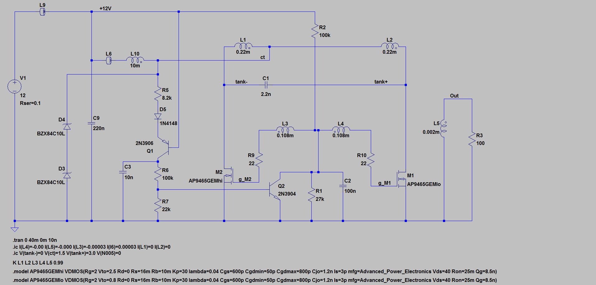
This is a version of the Baxandall parallel resonant Class-D oscillator built with N-MOSFET switches. Because it is designed to work with a 12V power supply, you can't get away with a direct drain-to gate cross-connection – the drain voltages have a nominal peak of 12π volts - 37.7V – which exceeds the +/- 16V gate-to-source maximum rating of the part shown, so the transformer has the usual Baxandall construction with a separate centre-tapped gate-driving winding.
The transformer L1, L2, L3, L4, L5 could be wound on an EPCOS ETD 29 core - the B66358-G-X187 (Farnell part number 1781876) is the cheaper N87 option. The centre-tapped primary - L1 and L2 - would be bifilar wound as a single layer of 10 turns of a twisted pair 0.85mm diameter enameled copper wire. Plus grade 2 enamel, it's maximum total overall diameter is 0.937mm, so 10 turns would fit as a single layer on the EPCOS flat-on-the-board B66359W1013T001 former. The MOSFET-driving centre-tapped secondary - L3 and L4 - would be wound on top as 7 turns of a twisted pair of much lighter wire - 0.2mm would do. L5 would be a single turn of wire. It's more a place-holder than a real winding, generating an output current through R3 on which I can run a Fourier tranform to extract the harmonic content.
I have added a start-up circuit, which progressively raises the voltage at gate-drive centre-tap to a voltage above the worst-case gate turn-on voltage at start-up, so the circuit is guaranteed to start up Once it has started up Q2 then pulls the centre-tap close to ground to give break-before-make switching when the circuit is running. The start-up time constant defined by C2 and R1 at 2.7msec is relatively long for a 100kHz oscillator, but it might be a bit short for a real power supply – they don't turn on instantly – and C2 might have to be replaced by small electrolytic in a real circuit.
It works well enough in an LTSpice simulation (click here to pick up the .asc file). The two switching MOSFETs have been modelled as having worst case high and low gate-threshold voltages. In real life, while the gate-threshold voltages wouldn't be identical, one transistor wouldn't be “on” for much longer than the other, and the second harmonic content of the output sine wave might be a bit less. The third harmonic distortion comes from L10, as in every other Baxandall oscillator and is the roughly 35dB below the fundamental, about 2%. L10 is an off-the-shelf part, which I could have bought ex-stock from Mouser Australia
D3 and D4 are a 20V Zener, designed to protect the MOSFET transistors M1 and M2 from seeing more than their rated 40V drain-source voltage at start-up. If the LTSpice simulation is anything to go by, they are inadequate – the V(tank+) and V(tank-) both peak at 43V during start-up. A more cautious designer would find parts with a 50V maximum rating, at least to explore real start-up behaviour
For a real circuit I'd prefer to use a digital scheme to control the gates, but that's a long way from the original Baxandall circuit.