Peter Baxandall described his parallel- and series-resonant class-D oscillators in 1959 in a paper in the Proceedings of the (British) Institute of Electrical Engineers (Baxandall, P.J, Proc I.E.E 106, B, 748 (1959)). I’ve got a copy here, purchased from the U.K. Institute of Electrical Engineers, who own the copyright and have given me permission to make it accessible on my web-site.
The circuit is useful for driving high turns-ratio step-up transformers – which have low self-resonant frequencies – used to generate high output voltages from battery-level inputs.John May has pointed out that C. J. Yarrow described a circuit very similar to Baxandall's parallel class-D oscillator in a paper (Yarrow C.J., Proc. I.E.E 106 B, 1320 (1959)) presented at the same conference where Baxandall presented his paper (if two days later than Baxandall presented his).
Yarrow's paper explicitly exploits the circuit for this application - it is titled "Transistor Converters for the generation of High-Voltage Low Current D.C. Supplies".
John has sent me a scan of the paper, which I haven't got permission to put on my web-site, but clearly I could forward a copy to anybody interested enough to ask for copy - strictly for private study, of course.
My suspicion is that Peter Baxandall might have thought up the approach, and got a sub-contractor to turn it into a product that Royal Radar Establishment would buy and use - putting a photomultiplier power supply into a high-flying aircraft does seem to be something they would have done.
The fact that the two papers showed up at the same conference does suggest it. The Yarrow paper incidentally details the process of winding a high-turns ratio transformer in a way that minimises it's self-resonant frequency - something that I got around to working out for myself, and ended posting some of the conclusions on sci.electronics.design in 2013 (see below).
In fact the copy of the Baxandall paper I display here isn't the one I got from the IEE (which wasn't a particularly high quality scan) but a rather better quality scan that John May sent me a few years ago. I'm clearly not the only person who finds the subject interesting.The circuit is probably best known from Jim Williams’ series of application notes for Linear Technology, on high frequency inverters for driving cold cathode back-lights used in laptop computers (application notes AN45, AN49, AN51, AN55, AN61, AN65). Jim Williams describes the inverter as a current driven Royer inverter, referring back to the non-resonant inverter described by Bright, Pittman and George H. Royer in 1954 in a paper “Transistors as on-off switches in saturable core circuits” in Electrical Manufacturing. AN65 does include a reference to Peter Baxandall, but to his 1960 paper “Transistor Sine-Wave LC Oscillators” in the British Journal of the IEEE paper number 2978E which is cited in a discussion of root-mean-square power measurements.
As Jim Williams points out, this circuit can offer good efficiency – 90% - when driving difficult loads. It is a rather cranky circuit, which works best if of the resonant tank has a Q of between 5 and 10 – according to Tony Williams (on the user group sci.electroncs.design Wed, Oct 1 2003 5:35 pm) and always produces a slightly non-sinusoidal output.
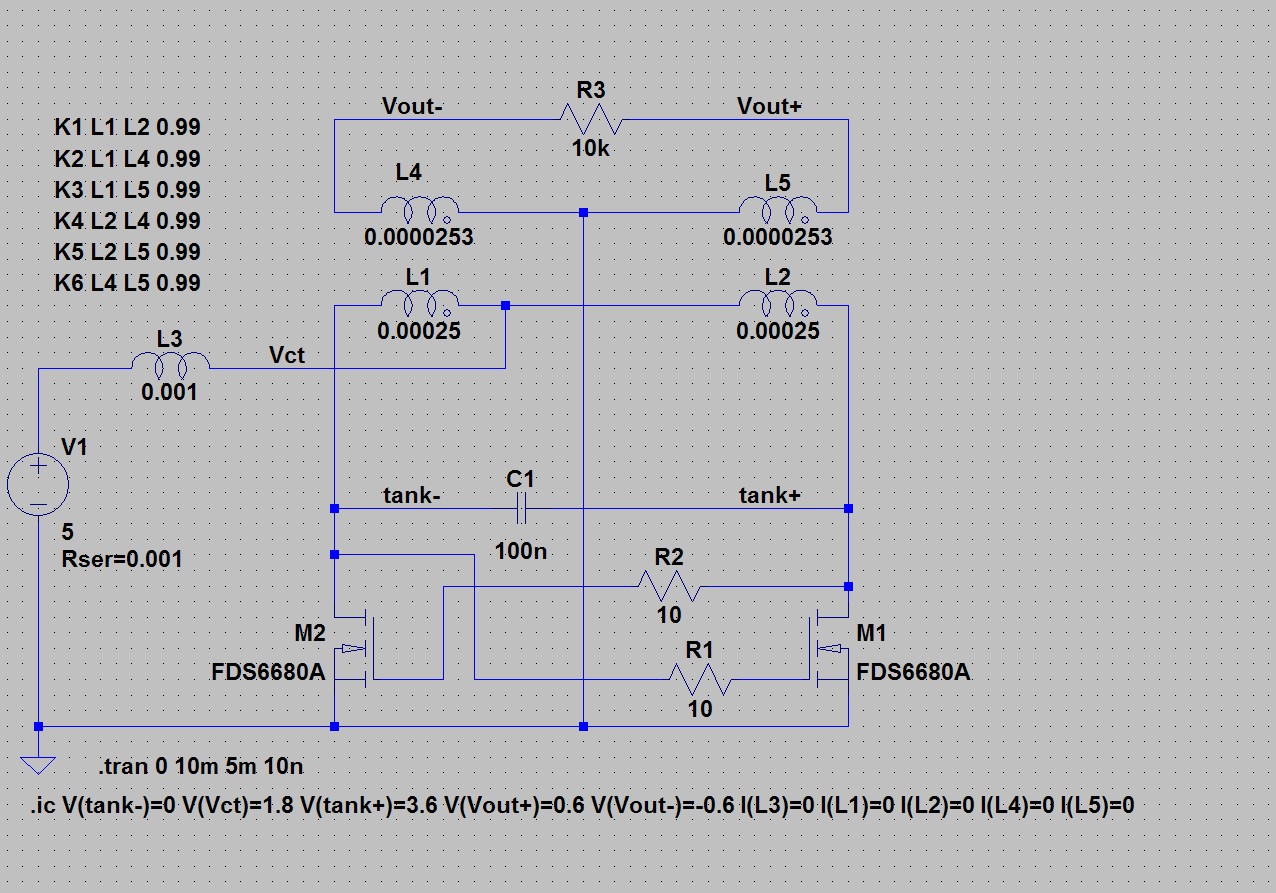
Here is an LTSpice model of a parallel resonant Class-D oscillator, set up to oscillate at 16kHz (100,000 radians per second). The transformer is to be wound on an un-gapped RM6 ferrite core. L1 and L2 would be ten turns each, and L4 and L5 only three turns. The 1mH inductor L3 would be wound on an identical RM6 core, with twenty turns of 24 SWG (0.56mm OD) enameled wire.
This is a very minimal circuit. Someone who cited this work claimed that it wasn't really a Baxandall Class-D oscillator because it didn't have the second base/gate driving coil. I've put together a version that has – and needs – a separate gate-driving coil
In Peter Baxandall’s original paper, it is claimed that if the inductance of L3 is set too high, it can be that the energy stored in the tank circuit never settles to a stable value, but rather “squegs” at a couple of kilohertz, giving a heavily amplitude modulated 16kHz output. I've seen this in circuits that I've put together, but it only appears only to happens when the circuit is driven with bipolar transistors, and seems to depend on some odd behaviour in bipolar transistors operating in the inverted mode – the Gummel-Poon model of the bipolar transistor doesn't capture this aspect of the devices' behaviour, and I've not been able to model it in LTSpice. The VBIC model, which LTSpice will run, might do better, but I've never been able to get hold of VBIC model parameters – semiconductor manufacturers treat this data as a commercially valuable secret.
I've been told that parallel-resonant Class-D oscillators never squeg when built with MOSFET transistor switches
The circuit shown, when simulated takes several milliseconds to settle down at start-up - the current through L3 exhibits a weakly damped (Q around 5) 5kHz oscillation.
Replacing L3 with significantly larger inductors in the simulation – 10mH and 33mH parts from the Toko 8RB range, 187LY103 and 187LY333 respectively - does not produce circuits which “squeg” and in fact both settle rather more rapidly than the traditional circuit, perhaps because their series resistance - at 40R and 80R - are much higher than the 0.044R of the L3 in the classic circuit above.
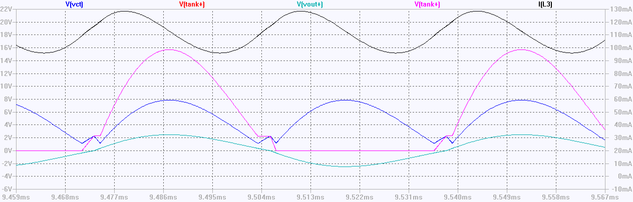
The operation of this circuit is simple enough – L1 and L2 form a tank circuit with C1, which draws current through L3. The crucial waveforms – at the centre-tap between L1 and L2 and at the drain of M1 – are shown below.
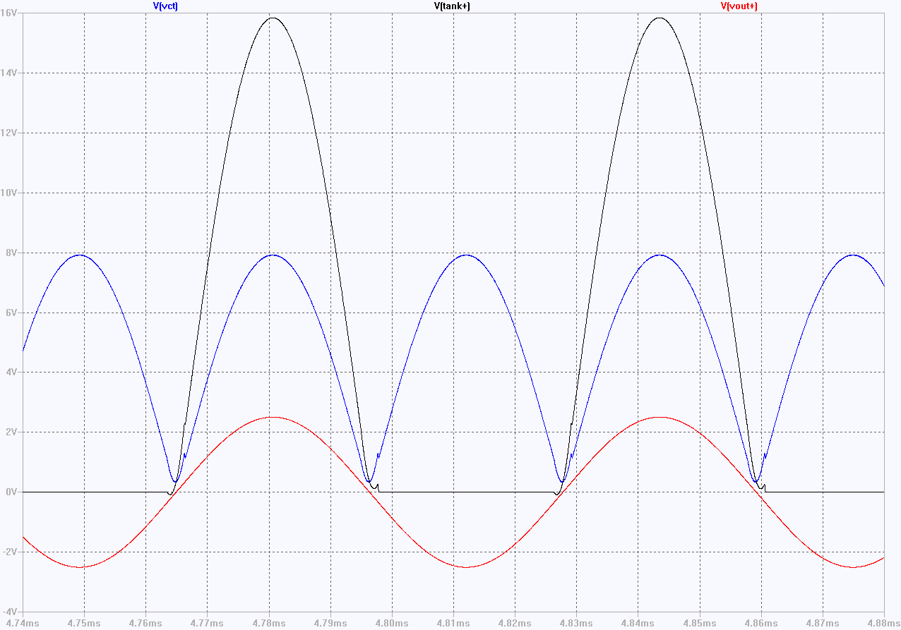
This generates a reasonably nice-looking sinusoid across R3 (the red trace Vout+ above), but with significant odd-harmonic distortion.
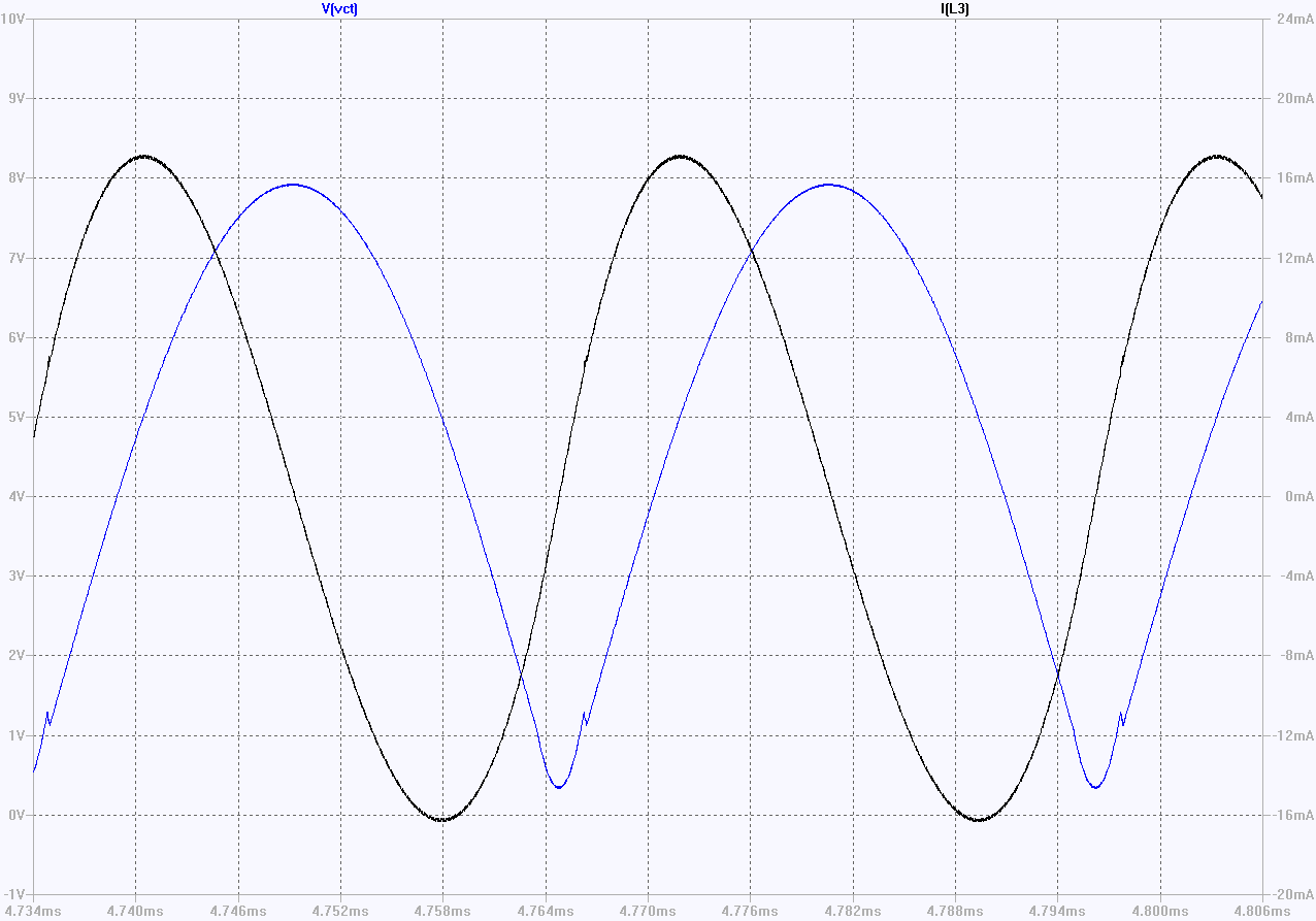
This is due to the relatively high second harmonic current (+/-16mA) flowing through L3, shown in the black trace below. The 0.2mA DC content of this current is all that is required to sustain the oscillation.
The distortion isn’t large enough to be visible on the waveform but it obvious in the Fourier transform of the simulated output below (red trace below).
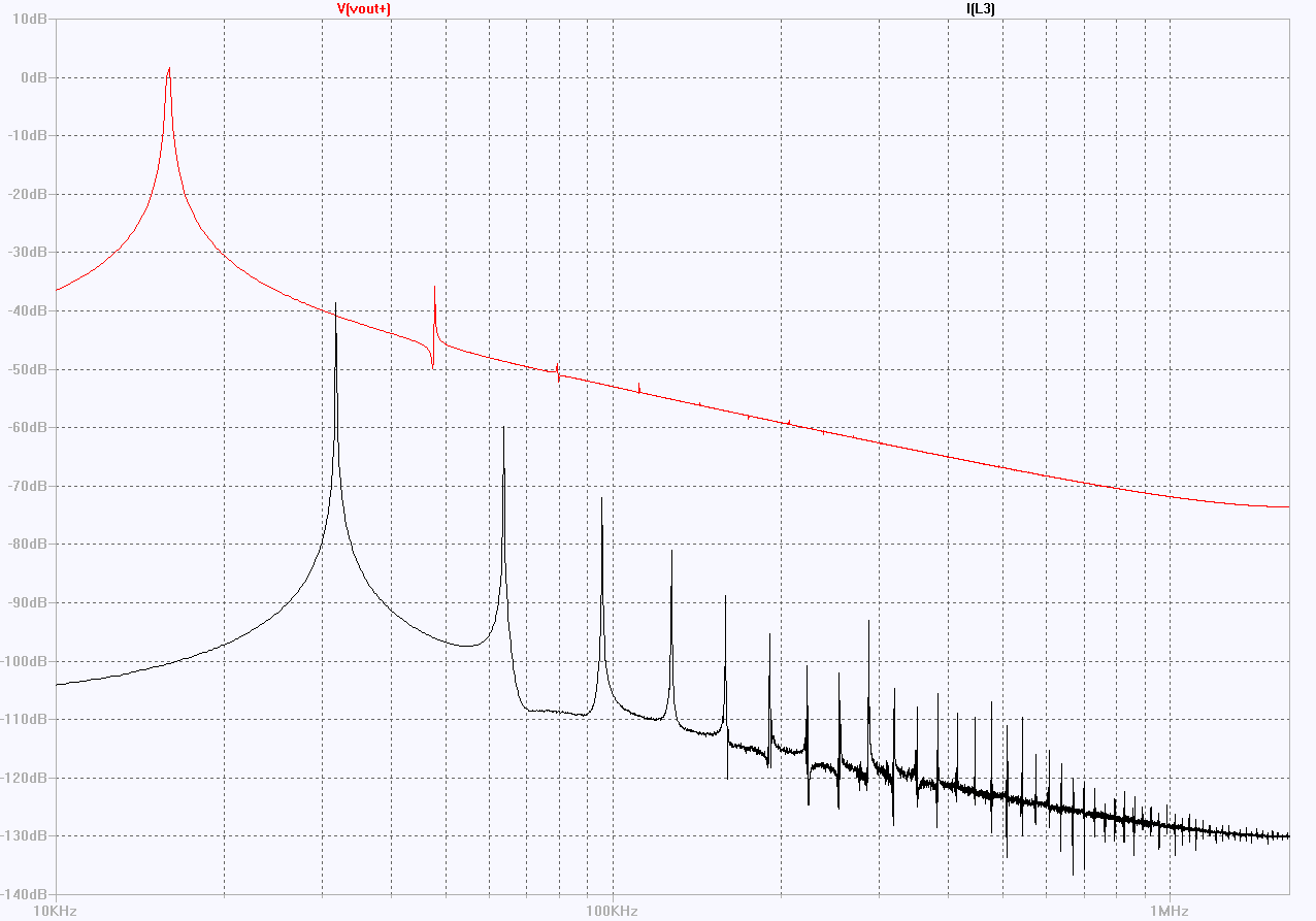
The Fourier transforms of the current waveform (black trace above) tells the story. The fundamental of the output waveform (upper, black curve) lies at 16kHz, while the fundamental for the current through the inductor L3 lies at 32kHz, as you would expect from the inspecting the voltage across L3 (in blue in both waveform plots above), and you get all the higher harmonics of 34kHz, which you would expect to get from the negative-going triangular segment of the waveform where the current is switched from M1 to M2.
The switches M1 and M2 effectively multiply the current through L3 by a 17kHz square wave – the squared up fundamental of the voltage across the tank circuit - and you get the usual sum and difference products of the components of the current through L3 appearing – as the odd harmonics of 17kHz – in the output waveform.
The high Q tank circuit formed by L1+L2 and C1 does an effective job of suppressing the odd harmonics – the 3rd harmonic is 42dB below the fundamental (0.8%).
Loading the tank circuit reduces the Q. and gives a much less sinusoidal output. Reducing R3 from 10k to 22R produces obviously distorted waveforms.
The current flowing into the centre-tap from the inductor L3 (black line in the above figure) is now feeding a relatively high amplitude square wave into the tank circuit, producing an output waveform with a much higher harmonic content.
This was discussed – in less specific terms – in Baxandall’s original paper, and is the basis of the late Tony William’s observation that the Baxandall class-D oscillator works best with a tank circuit Q of between 5 and 10. Increasing the Q of the tank circuit above about ten doesn’t produce any further reduction in the distortion of the sine wave output, decreasing the Q below five produces progressively increasing distortion.
The key to improving the performance of the Class=D oscillator lies in controlling the current through L3. Early on it was appreciated that adding a filter to block the second harmonic content before L3 improved the performance of the circuit for a tank circuit Q higher than ten. I’ve run simulations to show this.
You can also pulse width modulate the voltage being applied to L3 to create much the same effect as illustrated here.
Even LTSpice isn’t all that well adapted to running mixed analog-digital simulations, and I’ve got some ideas about how a real pulse-width-modulated variants of the Baxandall Class-D oscillator might be built and how they might perform.
And back in 1986, I invented a circuit which replaced L3 with a current mirror, which seems to allow you to get the higher-harmonic content of the output down towards the sort of levels you can get out of a Wien bridge.
This circuit was originally developed as a retrofit to excite a linear variable differential transformer used to measure the progressively increasing mass of a single crystal of gallium arsenide (GaAs) being grown in the Metals Research GaAs Liquid-Encapsulated Czochralski (LEC) crystal puller. The circuit it replaced had been developed a decade earlier and used components that had become obsolete in 1986. The new circuit replaced it in new machines and was retrofitted to some older machines.
It’s quite a bit more complicated than the Class-D oscillator, and less efficient – only about 50% of the power fed into the oscillator ends up in the load, rather than the better than 90% transfer you can get with a classic Class-D oscillator – but it’s quite a lot more efficient than any of the low distortion oscillators I know about, and it lends itself to very precise control of the output amplitude. I’ve generated quite a few Spice models of various implementations of the idea, but I’ve yet to get around to building a current version of the real circuit – the 1986 version worked fine, but at that time I wasn’t aware how good the circuit could be and didn’t have any reason to check out its performance in detail.
Here's a proof-of-principle simulation - which doesn't have anything in common with the 1986 circuit.